


Reliable power is key to ensuring comfort and convenience when you're on an RV adventure. An RV inverter is an excellent way to convert the DC power generated by your battery to AC power and use it to power your electronic devices. However, the installation process can be complicated. This article provides a comprehensive guide to help you understand RV inverter wiring schematics.
What is an rv inverter and why do you need one?
An RV inverter is basically a device that takes the direct current (DC) from the battery and converts it into the alternating current (AC) that household appliances use. This makes it possible to use all kinds of electrical devices in the RV. Whether you're into exploring remote areas or you're just into the whole RV lifestyle, inverters can really boost the energy efficiency and convenience of your RV.
Benefits of installing an rv inverter
- Provides AC power to support the operation of household appliances.
- Enhances off-grid capability to support camping
- Efficient inverter enhances RV energy efficiency
- Installing an inverter is a value-added feature for RVs
Importance of rv inverter wiring schematics
RV inverter wiring schematics are critical in an RV electrical system because they not only serve as a basic guide for installation, but also ensure that the entire system operates efficiently and safely. RV inverter wiring schematics show how to properly set up each of the inverter's electrical connections, including the inverter's input and output ports and its connections to the power supply, batteries, and loads, to ensure that the user is able to complete the installation process safely and accurately.
Avoid electrical accidents: Proper installation using wiring schematics prevents fires, electrocution, or equipment damage due to excessive current or grounding problems.
Improve system efficiency: The RV inverter wiring schematic plans the conversion path from DC to AC, ensuring that power is transferred by the shortest path and reducing energy loss.
Reasonable load sharing: The RV inverter wiring schematic allows you to rationally configure the power supply of different devices, avoiding the performance degradation of devices due to unbalanced loads.
Simplify complex connections: RV power systems often involve multiple devices and components (e.g., batteries, solar panels, inverters, generators, etc.), and wiring schematics can clarify connections and eliminate confusion.
Quickly locate problems: If a malfunction occurs while the system is operating, a schematic can help the user quickly locate the problem (e.g., broken wire, blown fuse, etc.).
Simplify maintenance: Technicians can use the schematic to quickly understand the system design and make efficient repairs and part replacements.
Facilitates future upgrades: When it is time to add solar panels, additional batteries, or higher power devices, the RV inverter wiring schematic can be used as a reference to guide system expansion.
Understanding the rv inverter wiring schematic
Whether you're a DIY enthusiast or a professional installer, knowing the wiring schematics will ensure a safe and efficient installation.
Components in an rv inverter system
To fully understand the wiring schematic, it is important to understand the major components of the RV inverter system:
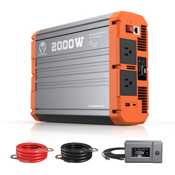
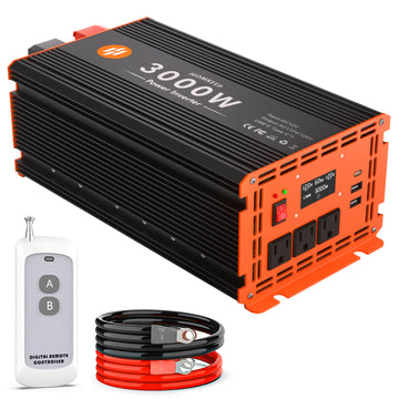
- Inverter: Converts DC power from batteries to AC power for use in electrical devices. There are several types of inverters, such as pure sine wave or modified sine wave inverters.
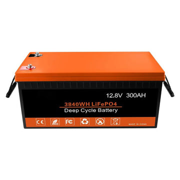
- Batteries: Batteries store DC power, usually 12V, 24V, or 48V, and are the primary power source for inverters. Lithium batteries are typically used in solar systems.
- Solar panel (Optional): Generates DC power to charge the battery when sunlight is available.
- Charge controller: Regulates the power provided by the solar panels to prevent overcharging the batteries.
- Shore power connection: Allows your RV to connect to the campground grid, bypassing the inverter, when power is available.
- Automatic transfer switch (ATS): Seamlessly switches between inverter power and shore power to avoid power interruptions.
- AC and DC switchboards: Distribute power to appliances, lighting and receptacles.
- Circuit breakers and fuses: Protect the system from overcurrent and short circuits.
Common symbols in rv inverter wiring schematics

Power supply symbol: Usually represented by two parallel lines, with one line typically marked with a "+" or "-" symbol, representing the positive and negative terminals.
Ground symbol: Usually shown as a line with three progressively shorter horizontal lines below it, representing ground.
Switch symbol: Usually represented by a broken line or a line between two dots, it may be SPST (Single Pole Single Throw), DPDT (Double Pole Double Throw), etc.
Battery symbol: Represented by a set of parallel lines, one short and one long, with the long line representing the positive terminal and the short line representing the negative terminal.
Inverter symbol: Usually shown as a rectangular box, possibly with positive and negative polarity markings or wavy lines to indicate AC output.
Wiring: Shown as straight or curved lines, with connection points between wires typically indicated by a dot.
Inverter connections: The wires from the battery to the inverter are usually thicker and marked as positive (red) and negative (black). Make sure the polarity is correct at the inverter input, usually marked "+" and "-".
Switches and circuit breakers: There may be a circuit breaker or fuse between the battery and the inverter to protect the circuit. The symbol is a connection between a short lead and a long lead with an "x" indicating that it is a circuit breaker.
Ground connections: All electrical equipment ground terminals should be connected to a common ground point, typically represented by the ground symbol.
Output connections: The inverter's output terminal is connected to the RV's distribution panel, possibly controlled by a switch for different appliances.
Step-by-step guide to rv inverter installation
When installing an RV inverter, having the proper tools on hand can make the process more efficient and safer while minimizing errors. The following is a list of tools and equipment that you may need when installing an RV inverter:
- Screwdriver set
- Wrench or socket wrench
- Multimeter
- Insulated gloves
- Goggles
- Electric drills and bits
- Leveling tape
- Measuring tools (tape measure)
- Battery cables and terminals
- Fuses and fuse boxes
- Heat shrink tubing or electrical tape
- Mounting brackets and screws
- Current clamp meter
Steps:
✔️Determining the location of the inverter:
- Well-ventilated: The inverter generates heat when working and needs to be placed in a well-ventilated area.
- Moisture and vibration resistant: Avoid installing in areas where water may accumulate or where vibrations are frequent.
- Close to batteries: Try to install the inverter as close to the batteries as possible to minimize cable length and reduce power loss.
✔️Preparation before wiring:
Before making the electrical connection, please make sure the DC switch of the inverter is in the "OFF" position and disconnect the AC side circuit breaker to avoid the risk of electric shock.
✔️Grounding:
Connect the protective grounding wire, connect the inverter to the grounding busbar through the PE protective grounding wire to realize the grounding protection.
✔️Fuse or circuit breaker installation:
Install a fuse or circuit breaker on the positive wire between the batteries and the inverter as close to the batteries as possible (usually not more than 18 inches).
✔️DC side wiring:
Connect the DC input of the inverter to the positive and negative terminals of the RV battery using appropriately sized cables, observing polarity, with the positive terminal connected to the positive terminal of the inverter and the negative terminal connected to the negative terminal of the inverter.
✔️AC side wiring:
Connect the AC output of the inverter to the distribution panel connected to the RV, making sure the wires match the rated output of the inverter. If the system has an automatic transfer switch (ATS), make sure the wiring complies with the instructions.
✔️Solar and charge controller connection (if applicable):
Connect the solar panel to the charge controller, and the controller to the battery. Make sure the input and output of the charge controller matches the solar panel and battery specifications.
✔️Inspection and operation:
Check that all connections are secure and verify that there are no loose or incorrect connections. Confirm that the connected loads (e.g., outlets, lights, appliances, etc.) do not exceed the power limit of the inverter. Ensure that the inverter is operating in a suitable ambient temperature, not exceeding 113°F, with good ventilation. Use a multimeter to test the input and output voltages of the batteries and the inverter for proper voltage.
✔️Power on test:
First turn on the batteries and observe that the inverter starts and operates properly. If the system includes a transfer switch, test for smooth switching between the inverter and utility.
Installation precaution
- Safety first: Make sure the inverter and batteries are disconnected from the power supply before starting work, and use insulated tools to prevent electric shock.
- Consult the manual: Each inverter model may vary slightly, be sure to follow the manufacturer's installation instructions.
- Periodic inspection: After installation, periodically check that connections are secure and batteries are properly charged to prolong the life of the equipment.
- Safety precautions: The inverter generates heat during operation; do not place objects near or on it. The inverter is not waterproof, so please avoid contact with water.


